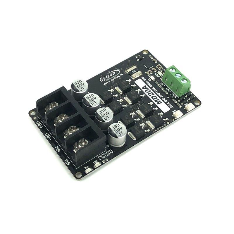
The diagram above shows an example diagram for using the L298N to drive one DC motor.

To drive the motor counter clockwise, the pin Input 1 is low while the pin Input 2 is high. To drive a motor to a direction, say, clockwise, the pin Input 1 must be high while the pin Input 2 must be low. The Enable A pin must be high to turn on the motor. For example, if a motor is using channel A, its terminals must be connected to pins Out 1 and Out 2. This IC drives two motors through two channels, A and B. It comes in two IC packages: MultiWatt15 and PowerSO20. The L298N is an integrated circuit that follows the H-bridge concept. This is very significant especially when using an Arduino board where the 5V power source is simply not enough for two DC motors. Нам важно знать ваше мнение.The other benefit of using an H-bridge is that you can provide a separate power supply to the motors.
#Motor driver controller generator#
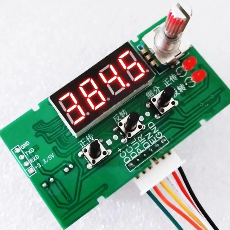
Please allow slight measuring deviation due to manual measurement.1 X PWM Pulse Signal Generator Доставка Due to the different monitor and light effect, the actual color of the item might be slightly different from the color showed on the pictures. The speed of the motor can be controlled by adjusting the frequency of the potentiometer.Specifications:Power supply voltage: 15-160V/5-12VFrequency: high: 5.8KHZ-127KHZ, medium: 590HZ-15.8KHZ, low: 82HZ-2.3KHZQuantity: 1pcProduct size: 73*51*37mm/2.87*2.01*1.46\"Material: plasticNote: If you use start or stop functions, ENA controller enabled terminals must be connected to common cathode or common anode drives.Notes:1.

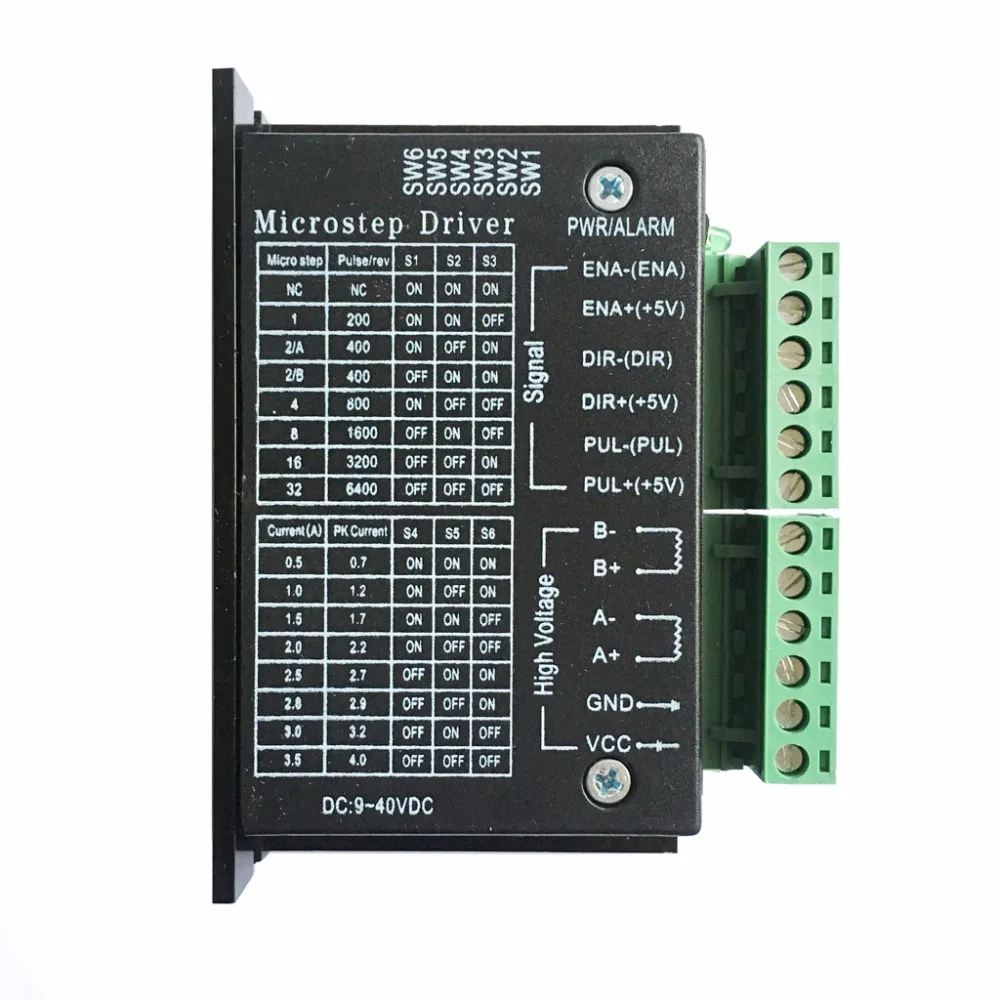
Press the key to control the forward and reverse of the motor. If a 5-12VDC power supply is used, the positive end is connected to the DC 5-12V input and the negative end is connected to the common cathode end. These six wires are connected to drive the corresponding pulse, direction, so six ports are possible.Power supply: 15-160VDC or 5-12VDC. PUL + and PUL - pulse positive and negative EN + and EN - for enabling positive and negative terminals DIR + and DIR - are positive and negative directions. The controller has three types of frequency signals: high, medium and low, which can be used to select jumpers. The measurement frequency can be two ports of PUL and common cathode terminal (GND). To control the stepping motor, a driver is also necessary. There are jumpers on the board, and the default selection provided in the pulse frequency signal can be set.Features:The module is provided as step driving signal.


The forward and reverse switching and on-off switching of the original motor are ordinary self-locking switches.7.The controller can generate PWM signal function. The speed of the motor can be controlled by adjusting the frequency of the potentiometer.6. The positive and negative rotation of the motor and the start and stop of the motor can be controlled by keystrokes.5. If it is powered by 5-12VDC, the power supply is positively connected to \"5-12V in\", and the power supply is negatively connected to \"common negative end\".4. 2 groups of power input, 2 groups only need to connect to one group of power supply.One group is connected to DC 15-160VDC.The other group was 5-12 VDC. Note that the ENA enabler on the controller must be connected to the driver in both positive and negative ways if the function of turn-on or stop is to be used.3. The six lines are connected to the six ports of the driver corresponding to the pulse, direction and enablement respectively. PUL+and PUL-are positive and negative of the pulse EN+and EN-are positive and negative of the enabler DIR+and DIR-are positive and negative of the direction. If you want to control the stepper motor, you must also have a motor driver.Frequency measurement: PUL and GND ports can be measured.2. This module is a pulse generating module, which supplies stepping driver as signal.


 0 kommentar(er)
